34 FORD
(Updated May 19, 2008)
QUICK FIND
THE FIND, THE START AND FIGHTING RUST RETURN TO TOP
 Carolyn's friend at Nordstroms department
store, Nancy, put us on to this one. The car belonged to her husband's ex-brother-in-law.
I talked to Nancy's husband, Russ, and he recounted a story that told about getting the
car started with a push in 1971 after the owner of the car (his brother-in-law) came back
from Viet Nam. The car had been parked under a pine tree for several years and was
completely covered with needles. It would not start on the battery but fired right up with
a push and it was driven to it's location in San Dimas. The brother-in-law moved shortly
to the Washington D.C. area, rented the house, and the car had been sitting ever since. He
said there was still air in the tires! Not too likely after 17 years but yet--. In the
last week of April 1987 I went to look at the find. It turned out to be a '34 Ford 5
window coupe. Russ took me to the car. I could not see it until I was within 3 feet. It
was completely engulfed in a honeysuckle bush. We parted the vines and sure enough--there
was a car. The hood was no where to be seen but it seemed all there except for minor
parts. My gosh! How can a 34 Ford coupe go undetected for 17 years in Southern California.
Well, the car had been driven into the back yard and then the occupant of the house
decided he was going to put in a swimming pool partly above ground in the side of the hill
in the back yard. The dirt from the project was thrown up to the top of the slope as the
pool excavation was dug into the bottom. The procedure steepened the slope a great deal.
Much too sharp to roll the car down. The pool was never completed. I suspect the intention
was to take the car out through the neighbors driveway by taking down a section of the
wire fence. However, the neighbor did not take to kindly to strange projects going on next
door that were never completed and a general lack of maintenance for the property. So no
one was on speaking terms. The car was stranded. No easy way to get it out, no way to
steal it or cannibalize it for parts. So it sat until the honeysuckle buried it. Before it
became invisible there were a steady stream of buyers that knocked on the door. After it
became invisible it simply sat while the weather took its toll and the top and interior
fabric turned into a rich mulch to grow more honeysuckle. This time rooted inside the car.
Since then the alley had disappeared and the car had been hidden from view by the
greenery. The present occupant of the rented house said that when they first moved in
(1971) people asked to buy the car several times a week but since the honeysuckle and
trees had grown up they had not had much of a problem. I wonder why?
Carolyn's friend at Nordstroms department
store, Nancy, put us on to this one. The car belonged to her husband's ex-brother-in-law.
I talked to Nancy's husband, Russ, and he recounted a story that told about getting the
car started with a push in 1971 after the owner of the car (his brother-in-law) came back
from Viet Nam. The car had been parked under a pine tree for several years and was
completely covered with needles. It would not start on the battery but fired right up with
a push and it was driven to it's location in San Dimas. The brother-in-law moved shortly
to the Washington D.C. area, rented the house, and the car had been sitting ever since. He
said there was still air in the tires! Not too likely after 17 years but yet--. In the
last week of April 1987 I went to look at the find. It turned out to be a '34 Ford 5
window coupe. Russ took me to the car. I could not see it until I was within 3 feet. It
was completely engulfed in a honeysuckle bush. We parted the vines and sure enough--there
was a car. The hood was no where to be seen but it seemed all there except for minor
parts. My gosh! How can a 34 Ford coupe go undetected for 17 years in Southern California.
Well, the car had been driven into the back yard and then the occupant of the house
decided he was going to put in a swimming pool partly above ground in the side of the hill
in the back yard. The dirt from the project was thrown up to the top of the slope as the
pool excavation was dug into the bottom. The procedure steepened the slope a great deal.
Much too sharp to roll the car down. The pool was never completed. I suspect the intention
was to take the car out through the neighbors driveway by taking down a section of the
wire fence. However, the neighbor did not take to kindly to strange projects going on next
door that were never completed and a general lack of maintenance for the property. So no
one was on speaking terms. The car was stranded. No easy way to get it out, no way to
steal it or cannibalize it for parts. So it sat until the honeysuckle buried it. Before it
became invisible there were a steady stream of buyers that knocked on the door. After it
became invisible it simply sat while the weather took its toll and the top and interior
fabric turned into a rich mulch to grow more honeysuckle. This time rooted inside the car.
Since then the alley had disappeared and the car had been hidden from view by the
greenery. The present occupant of the rented house said that when they first moved in
(1971) people asked to buy the car several times a week but since the honeysuckle and
trees had grown up they had not had much of a problem. I wonder why?
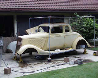
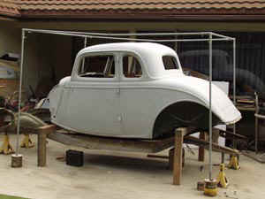
 Myself and two friends worked (more like an
archeological dig) on the project for several days and took the thing apart and CARRIED it
out of the property and loaded it on a trailer and took it home. I developed a bit of a
health problem that caused me to lose interest in almost everything. The body sat in one
location and the frame, etc. sat in another. The frame and engine were not worth saving.
But the body was another story. So when health returned, it was slid around the house by
cutting a gate post and I have been sand blasting the years of accumulated rust. The body
is not really in bad shape at all and the doors, trunk deck, front fenders and running
boards are nearly perfect. It is all there and destined to become a hot rod. My car
restoration helper, Frankie, was a ham this day and wanted to be in the picture.
Myself and two friends worked (more like an
archeological dig) on the project for several days and took the thing apart and CARRIED it
out of the property and loaded it on a trailer and took it home. I developed a bit of a
health problem that caused me to lose interest in almost everything. The body sat in one
location and the frame, etc. sat in another. The frame and engine were not worth saving.
But the body was another story. So when health returned, it was slid around the house by
cutting a gate post and I have been sand blasting the years of accumulated rust. The body
is not really in bad shape at all and the doors, trunk deck, front fenders and running
boards are nearly perfect. It is all there and destined to become a hot rod. My car
restoration helper, Frankie, was a ham this day and wanted to be in the picture.
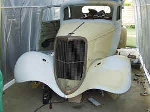
Here is some indication of progress in sandblasting. At this point
about 3/4 of the top down to the belt line is done. The sandblaster can be seen in the
first picture sitting inside the car. The second picture shows what a dramatic difference
there is from the rusted to the sand blasted areas. In both pictures the weld seams from
the original construction can be seen as well as the leaded section over the door pillar.
At this point the bare areas had been sitting out under a tarp for about a week. The
passivation appears to be doing its job. It took about a minute per square inch to do the
sandblasting. The worst part of the body (other than the rocker panel on the right) can be
seen to the right of the lower right corner of the rear window. The rusted through spot is
associated with a reinforcement weld to the inner body structure. So far, so good. There
are still a few sparks left in the old hulk.


Cleaning up the decades of rust and chemistry is very time
consuming. Sections of work seemed to be nearly impossible. A 20,000 rpm angle die grinder
proved to be extremely useful with Rollock disks and 3M "finger" disks. But some
areas were incredibly difficult. The section below the trunk and to the rear of the left
opera window was particularly troublesome. The surface looked like simple rust. But it was
rust that had permeated upward from the metal through some thin layers of turquoise blue
and black paint that was as hard as diamond. The angle grinder would just remove a puff of
dust before bogging down. Paint remover proved to be useless. Many tries with the sanding
disks and sandblasting was required before shiny metal was uncovered. The opposite panel
was very easy by comparison with white paint and primer coming off very quickly to reveal
factory fresh shiny metal underneath. The change of chemistry can be seen in the side view
just forward of the crest of the fender well. The section to the rear cleaned up
easily...like the same panel on the opposite side of the car. The section forward of there
to the rear of the door was extremely difficult but the underlying metal is sound and
shiny. Test patches were tried on the front fenders and the cowl. The cowl will be very
easy to clean up and the fenders won't be too bad.
Pictures show the right and left quarter panels and the trunk deck.
Compare them to the first picture(s) on this page. There are indeed plenty of sparks left
in the underlying steel. Don't give up with your rusted out hulk. It might have steel left
in there somewhere. In the face-on view of the trunk the worst part of the body rust can
be seen below and to the right of the rear window. And that is not all that bad. The right
rear quarter panel (resting on a 4X4) reveals the curtain lace that is left when the lower
edge of a quarter panel rusts through. That is also easy to repair with patch panels.
Some sandblasting is also evident on the trunk deck. In spite of
its hopeless appearance there is little damage to it or to the panel below it. Everything
will clean up bright and sound. Since steel bodies run several (7 or 8) thousand dollars,
the $500 dollar investment seems to be paying off. Who would ever have thought that the
bare metal would reflect images?
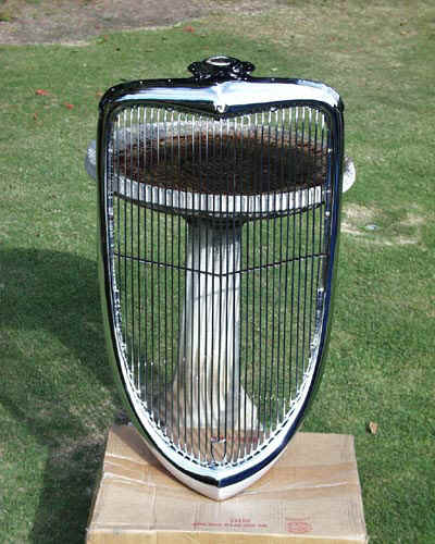
Some progress was also made on the radiator grills. I was fortunate
enough to acquire two grills with the car. It will take a lot of copper and much more
sanding to get them ready for chrome. But when finished the value of one of them should be
far more than what I paid for the entire car. One of the pictures shows one of the shells
after a LOT of copper has been added. At this point the shell has to be further
straightened, sanded all over and some minor repairs made with silver solder. It will then
go back to the plating shop for more copper or, if we are lucky, the final plating.
The following picture shows the results after a lot more work and final triple plating.


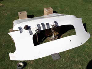
Both rear fenders were cracked about half way across at the top of
the wheel arch. The left one had been rolled in severely over about 40% of its length.
Work was started on the worst of the two by banging out the damage and welding the crack.
The left fender and running board was mounted to the body to fit in place. The gas tank
cover was added. The picture below and left shows the car in that condition as the sun
sinks in the west after a hard day of labor. The touch-up gun is seen lying on the edge of
the gas tank cover.

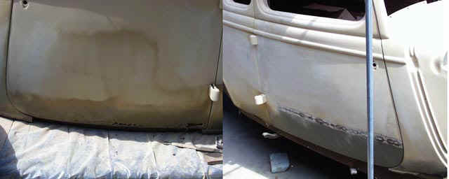
Just to give the reader an even better idea what it is like to
strip and refinish the metalwork on a 66+ year old car, progress on the doors is shown.
The first picture shows what the doors look like after they have been exposed to the
weather for at least 37 years and used as a chicken roost for about four years. The
resident bantam hen did her best to paint them. Diligent work with an angle grinder, 3M
bristle disks, roll-lock disks and wire brushes got the metal nice and shiny. It only
takes a brief encounter with the blow-off from the angle grinder to convince the restorer
that it is a good idea to avoid a direct hit in the face with rust and the ripe residue of
a pet chicken. The third picture shows the door after being re-hung for fit. No amount of
cleaning will remove the rusted through section at the bottom edge of the door. But a
patch panel is waiting for welding skills to progress to the point where it can be put in
place. The fourth picture in the set shows "before and after" versions of the
front fenders.


After a great deal of work the entire body was covered with several
coats of polyester fill catalyzed surfacer and imperfections dealt with one at a time.
Just to scope the amount of work that had to be done with spotting putty a picture of the
"de-freckle" job on the rumble deck is shown. Each dab of putty fills a tiny pit
in the metal where berries had fallen on the deck. Each pit had to be sand blasted to
bright metal and primed with etching primer before this step. A broadside quarter angle
view of the car is shown with a new hood in place and the fenders and running board
mounted. The running board is covered with plastic painter's drape to keep it clean with
all of the sanding on the surfacer. At this point some minor dents below the door belt
line are getting the finishing treatment. It appeared as if the driver was unhappy with
the car and worked it over with a fist or a "blunt instrument".

Here are before and after versions of the right door. The
door flew open at some point in the dim past and peeled some of the door skin back where
it hit the hinges. It also sprung the door sill (where the hinges attach to the
door) and broke the metal nearly all the way across. If that weren't enough, the car
sat for years leaning right and nose down so the lower edge of the right door was
particularly rusted. The patch panel is just "50% tacked" in place but I
am confident that my welding is good enough so that it will all work out. This is
TIG welding. The left and right doors are shown as "before" and
"after" to show the rusted out area and the patch panel. The upper and
lower hinges of the right door are shown as "before" and "after"
repair of the damage when the door flew open. No "pink lead". Just
hammer/dolly and sanding surfacer.
Somewhere along the line I decided that I had to have a target for all of this work ... an image ... a goal ... a dream. Something to reach for, to strive for, to measure progress against ... something almost real. I decided to create my dream and use it for the background image for the computer screen. I saw a nice black '34 5-window coupe at the Pamona Fairgrounds (the Los Angeles Fair Grounds). I took that picture and combined it with an image extracted from a picture that was taken at the Crane School Concourse De Elegance at Santa Barbara several years ago when Ferrari was the featured marquee for the year. My wife wore a dress that was made by my mother. She looked right at home with all of the elegant cars. We drove up in our '35 Rolls-Royce and were in the show with the rest of the Rolls-Royce/Bentley class. Carolyn was quite a hit. Photographers and car owners asked her to pose several times during the day. I needed a background for a fabricated theme picture and I happened to have a picture with dogwood in bloom that was taken about 1/4 mile from my dad's place in Illinois. I edited and combined the pictures in PhotoShop. The three original pictures and the composite are shown below. You just can't believe anything anymore. When I need some inspiration I only have to glance at the desktop screen to see where I hope to arrive ... someday.


CUTTING AND FITTING QUARTER PANELS AND ROCKERS RETURN TO TOP
Here is what happened over the Labor Day week end. I cut out the rusty remains of the
right side quarter panels and welded in new sections as well as a new rocker panel. Refer
to the first picture at the top of this page for the "before" view.
Two of the pictures show the weld lines for the quarter panel patches. The third is the
overall view.
I thought I was in deep yogurt with the rear quarter panel because it distorted so badly.
But, after a good night's sleep, I attacked with new "viga'". I fired off the
TIG welding torch and held it back from the metal so the plasma wouldn't melt it but just
get it good and red hot toasty. Amazing. What was an "outie" with the weld
turned into an "innie" with the shrinkage and judicious application of the dolly
and hammer resulted in what you see. It is not going to take a lot of filler to smooth it
out.
Next problem:
The door was bowed so it fit outside of the rocker panel in the middle. It could be pushed
back in to match with only a little pressure. I decided that the patch panel had to be
welded to the lower edge of the inside door panel (also a patch panel) with pressure
applied to put it in the right contour. That was done by simply pushing the door inward
(although open clear out at the time) and a vice grip was used (with a wood backer) to
squeeze the outer panel roll-over to the inner panel to hold the shape. I put in one spot
weld and ..... ta-da .... pretty good door fit. So I put in a half a dozen more spot welds
(more than Ford had) and it will stay put. Of course I sacrificed the primer and surfacer
at the spot welds but that is a small price to pay. By the way. The paint doesn't even
look harmed. But if you push on it, it is easy to see that it has become detached from the
metal. No problem.
The door fit was still not letter perfect. For this procedure you have to look at the weld
points on the tabs of the rocker panel. The "fix" is to take a big screw driver
point and drive the curve of the tabs closer to the body sill to pull the middle of the
rocker inward a tad.
The front end of the rocker and the rear end of the front quarter panel was completely
gone when I got the car. That part of the floor board and cowl structure was also gone. I
welded the repairs to that structure in place also including a new section of floor board.
It is all nice and solid once again. With a new firewall (Bitchin' Products) in place and
a new hood, everything is starting to look pretty nice.
Next time I will have all of the pieces all cut and fit so I can concentrate on nothing
but welding now that I have the procedure figured out. I think the left side of the car
will only take a leisurely week end rather than a hectic three day marathon. I have to
take advantage of my big Lincoln "loaner" welder more often. It just fits into
the back of the pickup truck even with the tool platform although it is about all I can do
to hoist it back out onto the cart.
The light at the end of the tunnel is getting REAL BRIGHT.


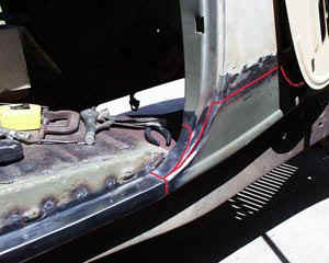
The right side of the car was in much worse shape than the left.
The front door pillar, cowl structure, the rocker panel and a piece of the floorboard was
rusted away as well as the bottom edge of the door and both quarter panels. How bad can things get? Water had collected in the region of the passenger's feet because the car was situated slanting down and leaning to the right. No metal was left under the right front window pillar at the floorboard. The entire panel was "swinging in the wind". There is a substantial reinforcement for the door pillar and it was entirely gone as well as a section of the floorboard. The first picture shows the right side forward door pillar and the entirely missing quarter panel and pillar reinforcement ... plus the floorboard which had gone AWOL. The next picture shows a cardboard mock up of the reinforcement that was made by using the left side as a template and "mirroring" the structure. The welded up reinforcement is also shown. From the outside a new quarter patch panel was fitted as well as a new rocker panel. The last picture in the series shows our pet bantam hen "Henrietta" inspecting the work in progress. She approved. A prospective hot rod project might use this massive rust damage as a worst case limit for restoration. It is surprising how good metal looks with a little sandblasting. However, when the metal is entirely GONE it does indeed mean that some extensive metal work and welding will be required. No glass. No "kitty hair". No half-way measures ... just metal replacement anywhere rust damage is so bad that the metal is either gone or won't clean up with sand blasting without making a sea of pinholes.


A hole had
rusted through below the right lower corner of the rear window. The right side was
repaired first as described above since it was the worst of the work. Then came the left
side and the rear window area. The following pictures show progress in those areas. The
first picture shows the section below and to the right of the rear window in the
"Frankenstein" stage ... with the two hand formed sections tacked in place. The
second picture shows the left door at the same stage and the third shows the left side
quarter panels, door repair patch, the rocker panel and a patched place in the left
forward part of the fender well completed.


Time marches on. There was a particularly
troublesome "oilcan" spot on the skirt of the left front fender. One of the
following pictures shows the fender after a "shrink session" with the
oxyacetylene torch and the next shows the fender after some more hammer and dolly work and
then sanding surfacer. There isn't much "pink lead" involved. And the hole
through and through under the rear window looks pretty good also.


RADIATOR SHELL FIT RETURN TO TOP
The first picture shows how much the fit of the hood and radiator shell can be adjusted by
raising the whole fender and liner and taking some metal off of the front of the fender
liner to allow the shell tip to move to the rear. The big fender brace also has to be
raised to allow it to contact the underside of the fender. I realize this "fix"
is a bit extreme but it shows how much the fit of the hood and radiator shell line can be
changed by pushing the associated parts around. Many of the cars that I see at shows
suffer from a large gap between the hood and shell. The fit is tight at both ends but
loose in the middle. The problem can be solved with enough work.

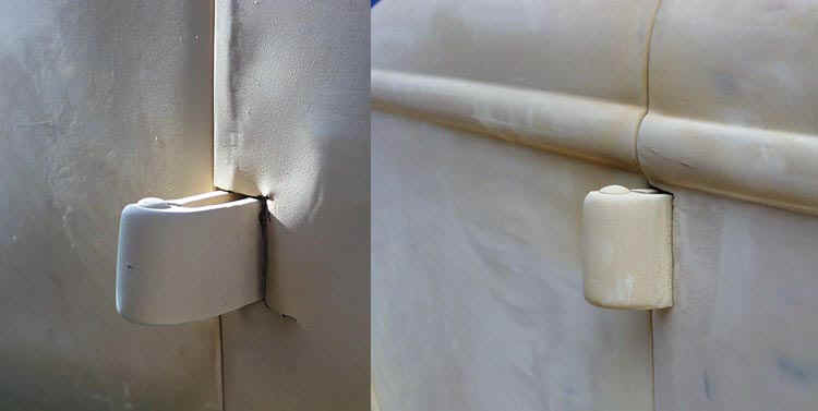
 The next picture shows the window "ventilation" system in its
various positions. This is the right (passenger) window regulator. The widow must be slid
to the right (towards the rear of the car) to crack the window at the front.
The next picture shows the window "ventilation" system in its
various positions. This is the right (passenger) window regulator. The widow must be slid
to the right (towards the rear of the car) to crack the window at the front.
The first picture shows the left gear cam up against the extension below the glass channel
rail (arrow) preventing the rail and window from moving to the right (open). Notice also
that (I think), if the widow mechanism had been cranked up further and and the window slid
open, that starting to lower the window causes the window to slide shut. I THINK this is
the way the window can be closed without touching it if it is slid open e.g. crank past
full up by a little slide the window open and then crank back down a little to close it.
The next frame shows the mechanism cranked further in the "down" direction. The
pin on the extension to the channel is just about to clear the cam.
The next picture shows the cam rotated a little further (down). The pin now clears the cam
and....in the next frame (second from bottom), the rail can be slid to the right cracking
the window. Compare frames 3 and 4 closely. Notice also that the window has not moved
appreciably downward since the arm tips are moving nearly horizontal with no vertical yet.
The final frame shows the mechanism when the window has been lowered about five inches.
Notice that the cam can engage the pin when the window rolls upward which (I think) might
return the window forward if it had been slid open when the window had been rolled down.
Clearly the glass dimensions have a lot to do with all of this cam timing. If the glass is
too high or too short, the rail and cam will not be positioned properly to do the job. If
the glass is too wide, it will not slide fore and aft and the window cannot be cracked to
ventilate the car when the window is fully up. I suspect some cars have window mechanisms
that are not operative simply because the glass was replaced by someone who did not study
the mechanism in detail.
I might have to cut a piece of Plexiglas using the new glass I have as a template to study
this whole behavior in more detail before I start putting things together.
Actually, the way the window works becomes much more obvious when the "work is at hand". Here is what happens. Starting from the "down" position, the window rolls up like any other automobile window. When the window closes entirely a continued crank on the regulator handle causes the window to slide to the rear into the extra-wide channel at the rear door pillar. This leaves a slot vent at the front of the window and ventilates the car for the 95% of the population who were smokers at that point in history. When the window crank is operated in the "down" direction, the vent slot first closes (window glass slides forward) and then the window rolls down as normal. The secret here is a "button" that is screwed or riveted inside the regulator channel track ... the silver part in the above pictures. The end of the left arm touches that button during its extreme travel (above fully up) and slides the whole track to the rear. The cam pushes it back forward. That "secret" button is not shown in the above pictures ... I hadn't "broken the code" yet. But here is a peek into the inspection hole in the door inner panel to show the arm and button in operation.
In the first picture the window vent has been pushed open by the arm striking the "button" (screw head) in the rail. In the second picture the vent has been closed by the regulator cam. The corresponding pictures of the glass are also shown. The LEFT side door regulator arm is shown with the RIGHT side glass so the relative positions are more clear.


Body work is not the only thing that has to
be done. Top bows have to be made and seat frames constructed. The bows at this stage were
deeper than they had to be, but it is a lot easier to remove wood than to add it. I used
BOTH seat slides from a Triumph for the bench seat. As it turned out, one pair of slides
on each side could use the existing holes. The seat sheet metal sides were constructed
from 16 gage and, like the wood, have been left oversize for cutting down later.


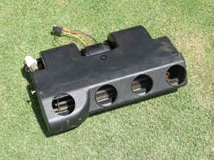
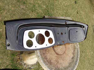
Dash instruments were fitted using a panel
CNC machined by a gunsmith friend. As you can see, I actually made schematics and
connector drawings before starting the wiring. Pictures of the fuse/relay box during
construction and as mounted are also shown. The first picture in the series shows the box
with some of the connectors mounted and the fuse panel with the fuse holders in place. The
second picture shows the fuse/relay box partially assembled. The next shows the box with a
backing rim attached and the last shows the box mounted in the left kick panel. The box
sports 13 fuses and four relays. While I was at it, I checked out the wiring and took a
picture of the lighted dash. Then I made a panel to carry a radio. It is STURDY. The
brackets that carry the radio are 16 gage and attach to the lower dash lip and the same
holes that hold the glove box in place.


I am, unfortunately, deeply into electronics as a "trade". And I like it!! .. oddly enough. There never seems to be an electronics application that does not get me interested and the '34 Ford project was not ignored. I have a lot of technical software on my machines. I hit on three projects for the car. First, and most complicated was a turn signal controller which would eliminate the mechanical nightmare associated with turn signal canceling using cams, etc. on the steering column. I didn't want a turn signal arm sticking out on a slender column like used on the old cars and I certainly didn't want the complexity of the associated mechanism. So I substituted electronics complexity for mechanical. The way the turn signals work is as follows. Two momentary contact and one single-pole-double throw toggle switches are located in the bottom edge of the dash to the left of the steering column. When the left momentary contact switch is operated, it starts the left turn signals blinking. If, while the lights are blinking, the switch is operated again, the turn is cancelled. If the signal is NOT cancelled, the circuit meters out a fixed number of blinks and cancels itself. The problem associated with a long stop waiting for a light is solved by inhibiting blink counting when the brake light is on. If the car sits with the brake pedal pushed at a light, the blinks while the brake is engaged is not counted and the count continues when the brake is released and the car moves on. The toggle middle switch performs the same operation for a right turn. If a turn is initiated in the opposite direction to one in progress, the counter is reset, the present turn is terminated and a blink count for the opposite direction is started. This solution positively eliminates continuous blinking if a "shallow" turn is performed (passing on a straight rode) and the driver forgets to cancel the turn. I figured if an automatic canceling scheme was good enough for old British cars (that use a clockwork timer), it was good enough for me. The right switch is for emergency flashers.
A picture showing the location of the three switches associated with the turn signals and emergency blinkers is shown below (red circle). The picture also shows the transmission temperature gage, instrument cluster and steering wheel. Two indicator lights are mounted in the transmission temperature gage ... a standard ignition "idiot light" and another to indicate when the torque converter is "locked up". The tachometer is perfectly hidden behind the steering wheel hub.
I designed and simulated the circuitry with software in my computer and then went through the trouble of making the artwork and etching printed circuit boards for the purpose. When populated with integrated circuits, the board worked "as designed" and all functions perform flawlessly. The pictures show the back and front side of the printed circuit board during checkout. The board is not fully populated with parts at this point. A bit of printed circuit artwork is seen adjacent to the board.


The next project was the creation of a windshield wiper controller which would hide behind the vacuum wiper cover which is located over the top of the windshield. The circuit uses no relays and implements the "interrupted" timed cycle familiar to all modern cars. It drives the motor mechanism that is available from Pacific Western Design, Inc. The picture shows the etch resist on the copper board material before etching in the kitchen sink. Since that point in time I have been using a commercial source for printed circuit fabrication ... much to the relief of my wife who never really warmed up to printed circuit board manufacturing in the kitchen.

I have one more electronics project to complete. After a lot of work making brackets and mounting external turn signals to the front of the car under the edge of the fender I decided that the little after market assemblies would not make me happy. So I have elected to add cowl lights to the "Standard" body and wire them for turn signals. However, that does not solve the rear turn signal problem. The "typical" solution is to cause one of the tail lights to blink completely off if the running and/or brake lights are on when making a turn. That has just never seemed to be an "elegant" enough solution to making three functions out of two filament bulbs with the standard rear lights. So I have designed a circuit which makes three light intensities available from the two filaments (not counting "off" such that a light will be present in both rear lights at night for the conditions of normal "run", braking, run with turn signal and run with brake AND a turn signal. The board has been designed and simulated but the boards have not been ordered yet.
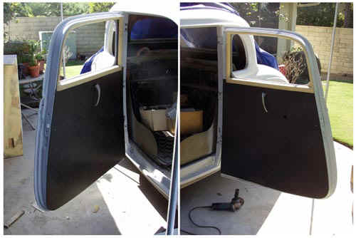
Ford uses a metal panel to cover the vacuum windshield wiper motor. I installed an electric wiper motor from Pacific Western Design. It fit just fine and worked well. But I wanted an "interrupter" function so the wiper speed could be controlled. The answer to that was to buy a controller from J. C. Whitney. It also fit just fine. To the left of the interrupter box I installed a toggle switch for the wipers and to the right I installed a three position switch for the dome lights ... always off, always on and automatic when the doors are opened. As it turns out, there was just enough room behind the door pillars and above the door check straps to install standard automotive dome light switches. The wiring was routed up and over the doors to the switch in the wiper motor cover (over-the-windshield) panel. It would be just next to impossible for one person to hold the panel up, connect wires to switches and connectors and then fasten the panel up with sheet metal screws. I simplified the installation problem at great expense in wiring complexity by routing the wires all over to the left side window hinge opening through the metal over the windshield where they could be accessed with the window cranked open and connectors plugged together. The wires were laced do that the panel and switches, the wiper motor or any of the individual components can be removed separately. The first picture shows the panel sitting upright and leaning against the edge of the window opening and shows all of the components and wiring. For orientation, you can see part of the steering column, column drop and the tranny temperature gage on the left. The second picture shows the wiring near the windshield pivot. The open hood can be seen out the windshield opening. The third pictures show the panel in place. That picture also illustrates the dome light mounting and wiring. This is all going to work out fine.


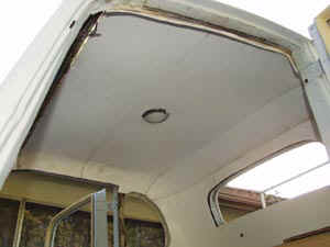
I discovered ABS plastic. The stuff is
addictive. It comes in plywood sized sheets. It can be used to make the most
wonderful stuff for hot rods. It comes in various thicknesses (at least two).
I used the heavier stuff for the door panels in the following pictures. It is so
much superior to the usual "cardboard" for this kind of application that there
is simply no comparison. Once you start making stuff with ABS, it is hard to
stop. It can be heated and formed. It glues with the solvent-glue that is used
to assemble toilet pipes and other plumbing. It is delightful to work with.
You just score it and when bent with a great deal of force, it will break right on the
score line. I went on from door panels to a complete headliner. Making a
headliner is about like waltzing with an elephant. It can be done but it takes a
long time because the "glue-up" has to be done in small stages and the glue
takes 24 hours to dry thoroughly. The final inside picture doesn't really show how
nice this came out because of all of the dirty fingerprints. Fear not, it will be
covered with foam backed fabric so the prints will not show. The whole headliner is
in one piece. It requires no fasteners. The front is held by the
over-windshield trim and wiper motor cover. The rear is held by the rear window and
quarter window trims and the top is held by the dome light.
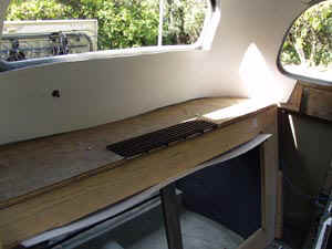
I had a major stroke of luck. My good
friend that owns a Jaguar garage called one day and said he had just removed an air
conditioner from an MGA that I might like to look at. Can you believe but it fits
right under the package tray where I had intended to put one? I then got carried
away with the ABS plastic to remake the ducts for the front and the rumble seat area side
panels and a panel to wrap around the conditioner to the bulkhead. The front end of the
conditioner panel can be seen sticking out of the bulkhead wood frame under a plastic vent
donated from a refrigerator. The vent is going to look nice. The front edge of
the panel is held in place with a plastic bracket that is now screwed to the framework (no
picture). Pictures follow:
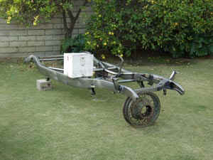
Finally the day came when the frame, which had been on order for
several months, looked like it would get done. So I hoisted the body high enough to
build a wood trestle under it in preparation for the new frame. Sure enough, the
frame finally got completed and two of us picked it up and carried it around the house to
the work area. I then slid it under the wood trestle and trial fit some of the front
suspension. It now looks like we are at the point where a lot of the remaining work
is nut and bolt work ... and writing checks.
Sometimes things just don't proceed in what
appears to be an orderly way. The next "order of business" is often what
gets the "juices flowing" rather than work in a category where you are
"burned out". Here are some examples. The first picture in the
string is a polished up water pump riser that puts a six cylinder Chevrolet water pump
about five inches higher than the normal small-block unit where the fan will do the most
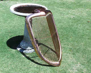
good for the high and narrow '34 style radiator. The next picture is the dashboard
after paint and polish lying on the bird bath in the back yard. The third is the
horns all ready for mounting. These little projects added some dazzle to the
drudgery of other work.
This kind of work lifts the spirits and
spurs the tired body on to more mundane work by giving a glimmer of hope for a completed
project that sparkles and shines.
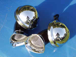
The old Fords don't have a lot of bright work. The following pictures show the refinished heater louvers, door handles and the horns. A picture of an original headlight housing with a new reflectors and lens is shown next to the beginning work on a radiator shell. Each shell required at least four passes through thick copper plating with a whole day of block sanding after each plating. The horns were treated to the same procedure. They are shown below after chrome but before they were masked and the portions that were painted black had been sand blasted. The result pays off in nice ripple free surfaces as shown with the completed radiator shell.


I couldn't leave well enough alone with just the usual bright work. I had to polish up the bat-wings for the front suspension. The parts supplied with the chassis were "as forged". The following pictures show a pair after just a little work with a flapper sander in an air driven tool and after several more hours of polishing. Not many people will ever see any of this but it is like "frilly panties" I guess. The owner knows.


I have never found after-market door lock "snibs" for the '34 Ford. So I had to make some.
Here are the stages in an angle-grinder "billet" machining job. Two more stages remain ending in 1500 grit wet-or-dry and at that point these will look like chrome.
The procedure is:
1) Get a mental image of what you want.
2) Select a piece of appropriate rough (1/2 inch aluminum plate).
3) Remove all material that does not match your mental image leaving the piece you wanted to make.
This is the same procedure used to make a gunstock or the statue of David. Different mental image, different material, different artist but the same procedure.


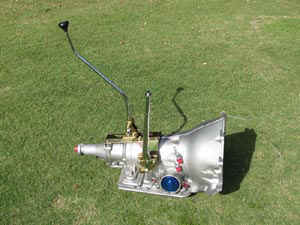
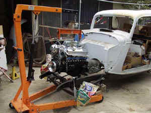
The next step was to get an engine into the
frame so that the radiator could be installed, a fan arrangement worked out and the front
bodywork fitted. The engine was down at Walt's garage where I was fitting an air
conditioner, alternator and various other pieces of bright work including the water pump
riser. So I got a 700R4 transmission for the project and fitted it with a Lokar
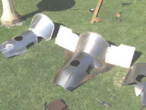
shifter ane emergency brake. It took four tries to build a tranny cover. The first one was done in
aluminum but we had a terrible problem with welding the pieces together. Any other
piece of aluminum in the shop would weld just fine but the material for the tranny cover
burned even with the nice Lincoln TIG machine and fresh gas. After enough cutting,
fitting and welding the tranny cover and toe boards finally fit in place over the tranny,
shifter and emergency brake. On to the engine work.
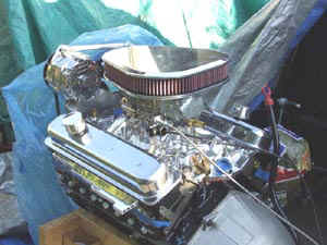
Then came the engine. I got a brand
new 350 HO crate engine and did the bolt-on work at Walt's shop. A two-plane Edelbrock polished intake manifold went on top and a Demon carburetor on top of that. The bolt-up is shown before the stock rocker covers had been replaced to illustrate the belt arrangement with the "auxilliaries". One adjuster bar sets the distance between the alternator and air conditioner compressor (top). The other (hidden behind the pump pulley and air conditioner sets the conditioner position and between the two of them, the belt tensions can be adjusted. The engine is sitting on the wood "crate" that makes it a "crate engine". The bottom pulley (Zoops) is a small overdrive from the standard diameter to increase the pump speed a little.


We strapped the
engine down on a four-wheeled dolly and the engine came home on Walt's trailer and I got
it down the trailer ramp and onto the concrete single handed. It rolled around the
house easily and I mated it to the tranny. A couple of weeks later I took home
Walt's hydraulic lift and got it into the chassis again single handed. I got a set
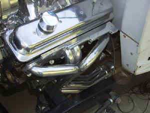
of Sanderson full-length headers and was pleasantly surprised when they actually fit.
I wasn't sure the headers would clear the SAC frame. The engine sports Billet
Specialties rocker covers, breathers and air cleaner, an Edelbrock dual plane intake
manifold and a Demon carburetor. The Pertronix distributor had to wait to be
fit until a "dimple" could be fabricated in the firewall to allow it to clear.
I had assembled several engines before this project with no timing problems. However, this one spooked me somehow. I had assembled the '35 Rolls-Royce engine that has five timing gears and it fired right up and I had it cruising down the freeway at 50 MPH within an hour of the first crank. With this one I fretted endlessly about getting the crankshaft damper on properly, getting the timing mark cover on the damper correctly, measuring TDC, etc. It was hard to feel #1 piston come to the top ... particularly when I had to turn the engine over using a pair of vice grips on the flex plate. Even when I was pretty sure #1 was at the top, I wasn't sure it was on the compression stroke so I took of the valve cover so I could observe the valve springs. I made every measurement I could think of and still wasn't confident. But finally I bit the bullet (after many hours of fitting the radiator, plumbing, etc.) and prepared to crank it up. But first I had to support the rear end from the rear axle because I didn't want somehow to start the engine with the tranny in gear with the wheels on the lift ramps and drive the thing off the wheel ramps and into the bedroom. I also wanted to be really sure that everything was fully lubricated before firing the engine up so I bought a pressurizing tool that plugs in where the distributor should go ... into the oil pump ... and spun it with a hand drill. The oil pressure came right up to 60 pounds in only a few turns. I then ran the pump with the hand drill for several minutes until all of the rockers were wet and oil was running down the channels in the heads and back down into the sump. I turned the engine a few times on the starter and then ran the oil pump another ten minutes or so. I was sure everything was as wet with oil as it was going to get inside the engine. I double checked the transmission starter interlock. Double checked the tranny linkage. Double checked everything and tried to start the engine. It wouldn't fire. For heaven's sake, how can that be? I decided that I had to have indexed the distributor 180 out so that the spark was occurring at the top of the exhaust rather than the compression stroke even after all of my measurements. So I pulled the distributor, rotated the shaft 180 degrees and plugged it back in. The engine started right up. The so-called initial timing was at about 30 degrees and it was easy to find the point where the engine was "happy" by simply twisting the distributor by hand and the timing was right where the literature says it should be and it responded to the vacuum line like it ought to. I finally let out the breath that I had been holding for about an hour and enjoyed the music. I checked everything out with a digital timing light and was happy that, as far as I could tell, the ignition was as it should be. The camshaft on the 350 HO engine is quite mild so the engine runs smooth and sweet with no lope at all at a quick idle. That is the way it should be for a "cruiser" so I was happy.
Want to hear the engine with the exhaust in place? The first file below is the second time the engine was started. The second file is a day later. I was being gentle to let the engine get some time on it at 2,000 RPM or so and with speed changes.
FIRST START HIT THE "BACK" BUTTON TO EXIT THE SOUND FILES AFTER PLAYING
DIFFERENTIAL AND DRIVE SHAFT RETURN TO TOP
I have a '92 Silverado pickup with a 350engine and manual shift and have found that it is disconcertingly easy to spin one wheel when starting up. I was sure that a limited slip rear end was a necessity and worth 50 hp. But differential prices were a bit shocking. Walt had a contact that claimed he could build up a differential for about $550 but after a six month wait nothing transpired. So I made a trip over to Currie and ordered up a nine inch Ford from them. A few days later I went over and picked up the third member. The ratio was chosen such that a nice cruise RPM would result with the 700R4 in overdrive ... something like 2200 RPM at 70MPH. The ratio is 3.5:1. Several RPM-speed calculators are available on web sites. The calculation simply involves figuring the distance traveled by a tire in one revolution from its diameter. The tire diameter may or may not be available from manufacturers web sites. In any case, it is a simple matter to calculate the engine RPM for any speed from the transmission ratios, differential ratio and tire diameter. Here is an on-site source: http://www.thirdgen.org/calculations . Do your own calculation and then check yourself with the site. It will help you to understand the "ins and outs" of gear ratios.
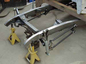
Bolting the 3rd member up was pretty easy and then came the "mystery" of setting the "pinion angle". Basically a drive shaft will have minimum vibration if the angle of the input shaft into the differential runs parallel to the crank shaft. That means that the spline at the front of the drive shaft should be parallel to the input shaft to the differential. That also means that the rear surface of the transmission should be parallel to the flat surface on the input side of the differential since the shafts and surfaces are at right angles to each other. Descriptions in the literature get things horrifically confused by addressing the angles between the crankshaft and drive-shaft and emphasize that the same angle should occur between the differential input shaft and the drive shaft. Forget all of that. There is nothing you can do about it anyway other than to change the rear ride height ... which is going to be willed on you by the tire clearance to the fender and the desired "stance". With the car carrying its own weight on its own springs, set the differential so that the input shaft is parallel to the crankshaft or the surfaces on both ends are parallel and you have done what you can do. The angle will change somewhat depending on how the car is loaded and how full the gas tank might be so load things up in a "typical configuration" if you are overly concerned.
One way to set the angles is to clamp a piece of wood to the input plate to the differential and another to the rear of the transmission and then adjust the rear suspension such that the distance between the wood pieces six inches up from the rotational axis and six inches down from the rotational axis are the same by tipping the differential forward or backward with the four-bars. Another way to do it is to use a magnetic indicator on each end to set the indicated angles to be equal. It is completely IRRELEVANT what the angle indicator reads as long at they are equal on both ends. After all, the car can be running up or down hill.
One other thing definitely affects drive shaft vibration and that is the relative rotational speeds of the various parts of the drive train and the weight and stiffness of the drive shaft. Vibration turns out to be about worst with an overdrive transmission in a car built to be a "cruiser". A light but stiff drive shaft is therefore a good choice so I ordered up and aluminum shaft from a local supplier after CAREFULLY making all of the length and yoke measurements. No, Virginia, all yoke bearings are NOT made equal and you have to have the right match at the differential. As luck would have it, I made an error and when the nice shiny drive shaft arrived, it would not assemble because the bearing diameters were not right. My error and I was prepared to pay for another whole drive shaft or at least pay to have a new rear yoke fitted. I was pleasantly surprised when the manufacturer had UPS pick up the wrong part and delivered a new one a few days later with no charge other than for shipping. Getting it fitted up to the differential was still a bit difficult because the bearings need to be "preloaded" against their seals to slip into place. That problem was solved by getting a big "C" clamp from Home Depot to apply a little squeeze while the parts were slipped together. Everything then went together "slick as snot" and the power was finally connected all the way from the engine to the wheels.
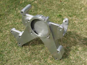
So here are the pictures related to the third member and drive shaft. Basically the mounting surface of the input yoke on the 3rd member (bolt holes in the picture on the left) want to run parallel to the flat on the output end of the transmission (where the splined tube on the left end of the drive shaft plugs in) and that will result in the input shaft to the 3rd member running parallel to the crankshaft. Everything else is broccoli.


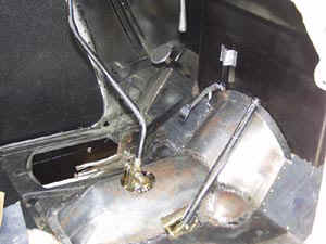
The Holley electric fuel pump is mounted on the left side of the frame tucked into the corner between the cross member and gas tank. It is bolted to the frame. The first picture shows the pump location. The back of the car is to the left. The fiew is toward the left side of the car. The pump exit is served by a blue AN fitting. The inlet has not been plumbed at this point but the inlet pipe runs from the pump up to the cross member and then downward at an angle to a custom made fitting (second picture) using the stock gas tank fitting. The custom fitting has a MUCH larger cross section than the original gas line so there is no restriction. The first picture also shows the rear junction block. The wiring is routed through a stainless flex conduit which is barely visible next to the top of the spring coils. The conduit runs all the way to the fuse/relay box which is mounted in the kick panel on the drivers side. The fuel filter is mounted on the frame opposite the fuel pump and is also tucked into the corner between the frame and tank. Yes, believe it or not, the fuel filter can be changed by reaching the retaining bolt on the top of the filter with an open end wrench. The fuel plumbing follows the cross member and enters the fuel filter at the front (left). The fuel exits to the right (rear), makes a "U" turn and runs over the cross member and along the frame up to the engine. The other aluminum tube at the left (front) edge of the cross member carries the wiring from the junction block on the left side of the frame (first picture) across to the right side lights.


UP FRONT (RADIATOR-FAN-ALTERNATOR-COMPRESSOR) RETURN TO TOP
Things are as tight up front in the engine bay as everywhere else in an old Ford. I bought a Walker radiator with a transmission cooler and air conditioner condenser. It went right in place and everything fit fine. The fan location in the old cars is way too low for modern engines. Recall that the original fan for Flat Head engines was located up between the banks at carburetor height where the air flow is centered on the radiator. Two alternatives are available to solve the fan location problem. The first (and used most often) is to use an electric fan or fans. For some reason this does not appeal to me. They never look "right" to me when they are mounted either in front or behind the radiator core. The other alternative is to use a "pump riser" to lift the axis of the fan by a few inches to get it up where it will do some good. That is the option I chose. The lift came from a maker in Pennsylvania. The stock Chevy water pump is NOT used. The cast aluminum riser uses a six cylinder Chevy water pump ... right out of an old Chevy truck or car. Yes, they move plenty of water. They are compact and cheap. The first picture shows the alternator and Sanden air-conditioner compressor. Those will have to get mounted somehow. The appropriate pivots and mounting points are built into the water pump riser. Everything including the riser itself is polished aluminum. The second and third pictures show the front and back side of the riser with the water pump, pulley and fan clutch. The fourth picture shows the assembly in place on the engine. The fan clutch is a commercial unit. The fins on the front of the clutch were milled off by about 3/8 inch to improve clearance. The pulley ratios (crankshaft/fan) are at a bit of an "overdrive" to encourage cooling at low engine speeds (stuck in traffic) which is where most problems occur.


The next problems are the radiator shroud and a means to adjust belt tension. I got an ABS plastic shroud from Walker. It, of course, was made for the standard pump location rather than for use with a riser. I cut the shroud in half and adjusted the height so that was properly centered using some additional black ABS plastic where necessary. The material simply glues together just like sewer plumbing pipe and is easy to work with. Right under the radiator tank the ABS is doubled all the way across to make it plenty strong. The fan blades had to be "pruned" a little but those big blades will still move a lot of air. Clearance is tight but adequate. The shroud is attached to the radiator side frames using brackets custom made to fit the attachment points provided with the radiator.
Now, how about belt tension? Well, I ordered some "spreader bars" from Zoops and fitted them up to the mounting bolts for both the alternator and air conditioner compressor. Some custom aluminum spacers had to be cut on a lathe and a fitting custom made to provide an attachment point at the compressor. The overall installation and the custom compressor fitting are shown in the final two pictures. The final hole in the special bracket had not yet been dirlled. The location was determined by a trial fit.
One of the spreader bars adjusts the distance between the compressor and alternator. The other positions the compressor with respect to one of the water pump riser fittings (down low). Getting the belts adjusted is done by adjusting both spreader bar lengths at the same time. The tension of the two belts is not adjustable without some interaction but that has not proven to be a problem. Removing belts cannot be done without removing a mounting bolt from the compressor to gain a bit more room. That is also not a big problem ... as long as you know the secret. The whole assembly ran as smooth as silk when the engine was started.
Proper belt length was found by simply making several trips to the local auto parts shop and trying several lengths until the right combination was found. Hoses are also a problem. I "shopped" for hours in parts places and never found hoses that would fit. However, I found a bottom hose that would work using a couple of stainless steel "stretcher" sections. The upper hose is a section taken from the top hose that fits my '92 Chevy pickup.
Notice the small spigot on the water pump. This is the so-called thermostat bypass path. It must be completed through a circuit to the heater or short circuited back to a fitting on the intake manifold. If that circuit is not present, lore has it that the pump will cavitate and not be effective. Hoses were routed back to the firewall where the heater will be mounted and used to complete the circuit until the heater is installed. No cooling problem was noted with a fresh engine idling and the car stationary. The water temperature climbs until the thermostat opens and regulates and then stays right at 185 like it should. This is a LOT better than the cooling that I had experienced with early 30s Fords back in the '50s when they insisted on boiling constantly ... winter or summer, uphill or downhill, rain or shine.


I did some considerable shopping for steering columns and related equipment and was not happy with anything I could find. First of all, I wanted to retain the look of the "slender" columns used in the old cars. I elected to make my own. I thought out the bearing and mechanical arrangement and got small quantities of materials from http://www.onlinemetals.com/. All of the various diameter and wall thickness pieces of aluminum arrived in a few days and I made up the steering shaft and column using a 19th century lathe owned by a friend. The first picture shows the various pieces of the assembly. There are other smaller sleeves and spacers not shown here. Both ends of the shaft are supported by sealed ball bearings. A quick disconnect spline is welded on the "business end". A picture of the completed and polished assembly is also shown.


A commercial steering wheel drop is used. I made a slip-ring pickup from PVC pipe and a copper pipe fitting and fixed it to the shaft with set screws (not in place in the picture). The upper ball bearing is in place. The bottom bearing is not. The circular object lying at the left end of the shaft is a ring clamp which holds everything in place at the bottom end. The splined end of the shaft is gun barrel drilled far enough for the horn wire to get around the upper end bearing and exits through a cross hole and is soldered to a tab on the slip ring. The three holes in the column main tube right at the slip ring are to mount the spring loaded pickup which is shown in the following pictures along with the slip ring insulator before threads had been turned off with the lathe. The pickup is from the steering column of an MG. It plugged in under the horn button and ran parallel to the steering shaft. In this application it is mounted at right angles to the shaft and is hidden behind the column drop. The threaded sleeve was improvised from a standard hydraulic fitting and is epoxied onto the body of the spring loaded pickup. It screws into place in a saddle piece which is, in turn, attached to the main tube with two button-head allen screws.


A sturdy yet simple method had to be devised to attach the bottom end of the column to the floorboard. I used a stainless steel muffler tube clamp mated to a hand made steel bracket to solve that problem. Loosening the clamp bolts allows the column to be easily removed (as easily as these things ever get) while providing a very sturdy attachment. The clamp by itself and when bolted down to the floorboard with the associated bracket is shown in the following pictures. You can also see the dimmer switch.


The next step was to make a connection from the output end of the steering shaft to the Vega steering box. Things are very tight with the full length header. Three universal joints are required and I also used an anti-vibration fitting. With three universal joints an idler bearing is required. The whole assembly is shown in the following picture. The large bolt on the idler bearing is attached to the frame using bolts associated with the four-bar suspension brackets and a custom bracket made up from standard steel angle material. The view from the driver with a Grant steering wheel in place is also shown.


I started from the front and worked to the rear. The first order of business was to get a manifold/headers. I researched the subject and called Sanderson to help with the selection. They had a model that was supposed to fit. The GM engine documentation recommended a two and a half inch system with full length headers and a crossover pipe. I ordered Sanderson full length headers and they arrived promptly and, even though it looked like it was pretty much impossible to get them in place, they sent right in. The headers can be seen in the above picture and in the first picture below (before being installed). There was a bit of a problem however. The exhaust could not continue straight back unless the 2 1/2 inch pipes threaded their way though the frame tube cage ... which would leave only a scant half-inch clearance up and down. The other option was to route the exhaust under the frame tubes and back to the muffler position where they wrap back upward. There is no sacrifice in ground clearance with that route so I went with it. The second picture below shows the four transition pieces that were welded up from a set of "builder" stainless pipes (several 45/90 degree bends and straight sections. I figured out how to do all of the routing without more material and we leaned how to weld stainless. This ain't rocket science and this car is meant to be a "cruiser" rather than a hanger-queen that sits on a mirror at shows so perfect welds and polish was not a necessity ... but it came out pretty well anyway. Believe me!!!!! Getting the collector transition from three to two inches belled to go through the flange was a nearly impossible job. No amount of hammering on the red hot section would get it to stretch up from 2 1/2 to three inches. So we gave up and went down to a friendly muffler shop who used their hydraulic machine to coax it to fit. The end was then bent outward to make a flange which was welded to the bigger 1/4 inch thick flange which bolts to the header. This was a major operation and would still require some slitting and fitting and also fitting in a crossover pipe.


Each piece of the job had to be cut and ground and fitted in place on the car to get everything to work. The first picture below shows the view looking forward at the left-side muffler (also stainless) and the exhaust pipe as it wraps around the frame tube. The magic marker black stripes are there to allow the pieces to be positioned properly for welding. This is a whole lot of work in cramped quarters under the car. You can also see the master cylinder and power booster (gold) in this picture and the splined exit shaft from the 700R4 tranny which is protected by the red plastic cap. The right picture shows the transition up and over the axle. At this point the 3rd member was not in place. You can see both of the right four-bars and the rear attachment pivots. The view is downward past the rumblseat cushion springs. Everything is covered with dust from paint filler sanding. The last floorboard section is still not in place ... which made working under the car in this region a lot easier.


The crossover pipe was difficult. The GM instructions and hot-rod literature extol the virtues of a crossover pipe to squeeze out horsepower and even out the exhaust note. So I gave it a try. The first picture shows one of the collector and transition pipes cut to match the crossover. This took dozens of tries under the car with fitting and grinding to get things to fit. The pipe has to run between the engine oil pan and the front of the transmission. There is nowhere else for it to go. Things have to fit just right so that the exhaust pipes are level, the flanges to the collector line up properly so they will seal and the distance between the pipes has to be right spot-on. The second picture shows the right and left sides welded up and everything ready to bolt up.


The Flow Master mufflers fit and all of the pipes went together well. It remained to find a way to hang the tailpipes. My solution to that problem was to weld up a bracket using standard muffler hangers ... one steel for the rear spreader bar and the other stainless for the exhaust pipe. The two go together with a silicone hanger grommet from Summit racing. As you can see, the snuggle up tight under the gas tank with no wasted space. It DID sound good when I fired up the engine. I am going to have to figure out how to make a link to a sound file.


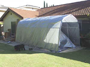
Winter was upon me. It is very
annoying to have to drag tarps onto the project every night. I got a
"Hindenburg Hanger" from a friend of Walt's who had purchased three of them from
Harbor Freight. I assembled the thing in the back yard and then slid it by stages to
behind the project and then over the car like the whale swallowing Jonah. It works
pretty well. Rain water still floods the concrete and stops the work but it keeps
off the dew. It is a bit crowded but that is not too bad. It was now time to
do more fitting on the front fender liners after the radiator and fan was fitted (Walker
radiator and a non-thermal mechanical clutch/fan from Flex-a-Lite). It all fit ...
just barely. The fender and radiator shell fit is pretty good ... very much better
than a lot of the similar cars that I have seen. Here is the Hindenburg Hanger and a
front view of the car with the fenders and hood in place.
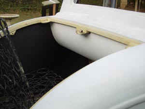
I have always loved music and had always wanted to have a good sound system in a car so I started on that project for the '34 Ford. I started by installing a power amplifier in the plenum in the bulkhead that would provide inlet air to the air conditioner. I fitted a pair of 6X9 inch JBL 3-way speakers in the package tray. The speakers are in their own sealed enclosure. Under them and in the rumble seat side panels are mounted a pair of ten inch Peerless Sub-woofers. Although not shown in these pictures, there is an equalizer with an A/B input switch mounted along the direction of travel of the car and along side the left edge of the air conditioner ... about even with the left edge of the amplifier. The equalizer control knobs point upward and make a pleasant blue glow in the dark. The audio signals from the radio are routed up through the right windshield pillar, over the door behind the headliner panel and to the equalizer. A miniature stereo audio cable with RCA terminals on the far end provide input from an MP3 player to the second input pair of the equalizer. The A/B switch selects either signal source. The MP3 player is loaded with 60 Gigabytes of music ... enough to play non-stop without a repeat for approximately 30 days. The second picture shows the right side rumble seat panel with the 10 inch speaker in place. A piece of floorboard has still not been installed at this point. The large hole below the rumble seat lid edge is an opening for a built-in tool box ... one for each side. The air conditioner evaporator (black) can be seen extending below the rear window tub (green). Just to the right of the air conditioner and above the speaker is a "former" which defines the radius of the cover for the air conditioner. More on that later.


The big problem was finding enough volume for the sub-woofer "boxes". Clearly there is very little space available and the calculated sealed box volume for the speakers and recommended by the manufacturer is 2.2 cubic feet. It dawned on me that there was barely 2.2 cubic feet in the whole car interior ... '34 Fords are not exactly limousines. The box volume has to be sealed. So here is how I did it. I made a "bulkhead" shaped like a half violin to go in right at the trunk/rumble seat steel strut that runs from the floorboard up to the deck rain channel to seal off everything forward of that point. I constructed an approximately 1/4 round section of laminated plywood (two layers of 1/8 inch) to seal off the volume to the right of the former mentioned and shown above ... over to the rumble seat side panels from each side of the air conditioner The volume forward of the bulkhead behind the seat (left picture above) and up to the body door pillar was added to the other volumes. That still was not enough so I made laminated plywood panels which seal up the volume from the package tray up to the top of the rear window and around to the quarter panel windows (the windows that make it a 5-window). The TOTAL of all of these volumes is 2.2 cubic feet measured the hard way by pouring packing plastic noodles or acorns into all of the spaces and then digging them back out a handful at a time. From experience, it takes about an hour to retrieve 2.2 cubic feet of "noodles" a handful at a time. The volume was verified by putting the noodles back into a plastic box and calculating the product of the length-width and height of the sea of noodles.
All of this is greatly complicated by the fact that everything must be capable of disassembly so that repairs can be made by some hapless soul sometime in the next century. I have been careful to write down a "cook-book" to guide that future person because it looks like that taking things apart could only be done with a sledge hammer and chain saw ... but it WILL come apart.
So here are the parts that make up the speaker volume. The first picture shows the "violin" shaped piece that seals off the speaker volume from the middle of the rear fender well forward. It has a quarter round section on it which the rumble seat side panel screws to and keeps it from rotating. The "neck" and along the edge is screwed into from the vertical steel strut in the rumble seat area. The actual seal is done with "Damplifier" sound damping material which is pressed onto the entire inside of the body shell and around the appropriate corners. It sticks tenaciously. The second picture shows the 1/4 round section which is made up from two layers of 1/8 inch plywood laminated together. It "plugs into" a slot in the rumble seat side panel so it can be removed yet be air tight. Along its inner edge it is screwed to blocks which are glued to the sides of the "former" which defines the air conditioner cover radius. This piece extends the speaker volume up to the air conditioner on each side. The last two pictures show the plywood quarter panel wall which extends the speaker volume upward along the rear window behind the head liner ... which is made of ABS plastic and goes in over the plywood panel. The final picture shows the "shepherd's crook" piece that is screwed to the top of the rear window frame and defines the top of the quarter panel volume. The plywood is screwed down along all four edges to make a solid and air tight volume. Small problem areas are sealed up with GE RTV sealant and the entire speaker volume is lined with Damplifier. Isn't this a heck of a lot of work to get 2.2 cubic feet of speaker box volume?


Now is a good time to point out that there are metal pieces riveted to the rumble seat side panels which receive upholstery fasteners that are affixed to ABS panels which will be finished in leather. This approach is used throughout and allows all of the upholstery to be put in place with no visible fasteners.
The plywood quarter panels (speaker box seal) need doubled to make them 1/4 inch thick. Gluing doublers to a big piece like this is pretty much impossible but smaller pieces can be glued on with some considerable trouble. The following two pictures show gluing a doubler on the bottom edge of the left side quarter panel plywood (left above). It always seems that I use 100% of the available clamps for every operation ... and I have about 15. (I really didn't use them all in this operation, but close.) The bottom radius is defined using the left side package tray speaker panel as a template. It took eight hands to hold this all together while the clamps were all tightened up (and I only have two) and the white glue squeezed out showing that the entire surface was pulled up tight. Today I also put "Damplifier" in place all the way to the original top bow (left above). The top bow is not used because the headliner is all ABS plastic but I will leave it there anyway. I got the screw holes drilled in the "shepherd's crook" pieces (right above) and pilot holes drilled into the top wood frame for the rear window. I had to use a 1/4 inch wrench to turn the pilot drill in the rear window frame because there is no room to use a power tool from above because the top rolls forward too fast. Fortunately I had a drill and countersink set that has hex shafts which can be turned with a wrench. It sure takes a lot of turns with a wrench to drill an acceptable hole.


Here is what makes a hot-rod project a hot-rod project. Just like with the tranny cover, it took several tries to get it "right". With the panels on the sides of the quarter windows it took several tries to get the plywood "right". And then I thought about it for just a minute or two and pulled them back out and used two pieces of that hyper stiff aluminum stock we tried to use to make a tranny cover to make the panels and abandoned the plywood approach. Well, it would have been a major thing if I had been "paying for the work". But since my work is free (and worth every penny) nothing was lost except my time and a few drops of blood. This is not done yet but the picture shows one of the aluminum panels. It is so stiff that it is nearly impossible to bend it over a knee. I will wait until I route a radio antenna cable over the quarter windows and spot tie the electrical wiring at several places before I screw it down. I am as happy as if I knew better in spite of the major amount of work that went into bending plywood. Notice the knobs for the equalizer next to the edge of the speaker plate. The A/B sound source switch and a level control is also included. The equalizer is mounted on the right side of the air conditioner so that it is a comfortable reach from the driver's position.
